Can carbon fiber parts be drilled and bolted directly? How should a carbon fiber tube be connected to a metal fitting? And how should a joint be designed if it needs to be assembled and disassembled repeatedly?
Joining may seem like the final step in assembly, but it can become one of the most vulnerable areas in an entire carbon fiber structure.
The reason is that carbon fiber composites have distinct directional properties and a layered structure, so their load-bearing and damage mechanisms differ from those of metals. Drilling cuts continuous fibers, excessive bolt tightening can cause local crushing around the hole, and too much clamping pressure may damage the tube wall. When carbon fiber is in direct contact with metals such as aluminum, galvanic corrosion must also be considered in humid environments.
So the real challenge in carbon fiber joining is not simply “how to fasten the parts,” but how to transfer loads smoothly through the joint while minimizing damage to the original structure.
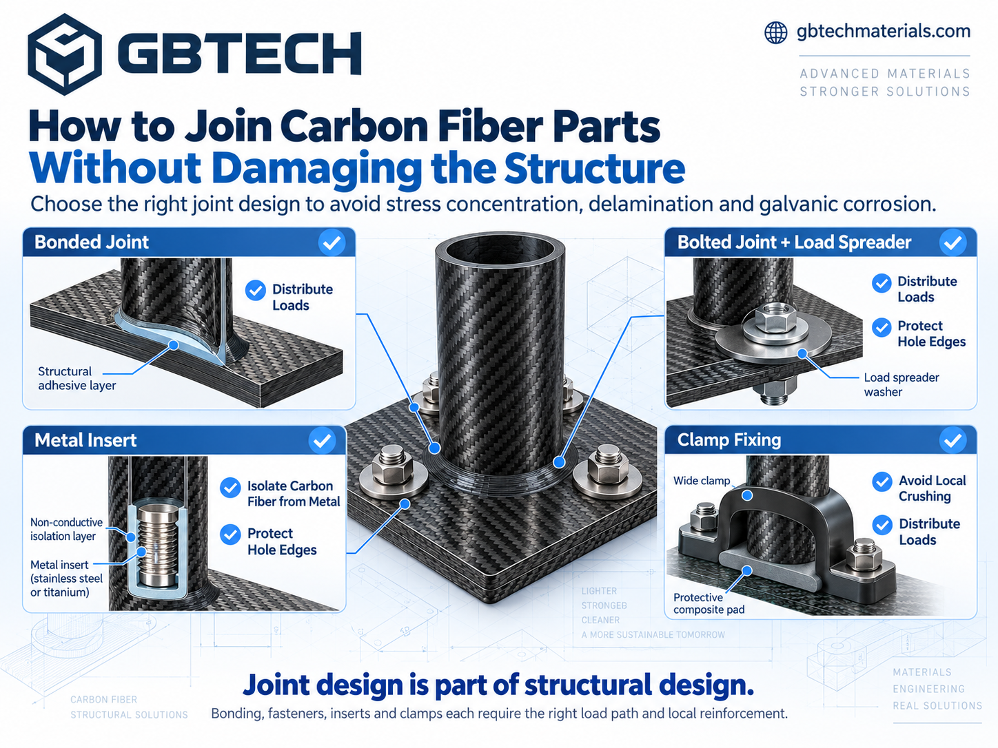
Adhesive bonding is suitable when preserving continuous fibers is a priority. It requires no drilling and can transfer loads over a relatively large bonded area. It is commonly used for joining carbon fiber sheets, tubes and sleeves, as well as carbon fiber to metal components. However, a reliable bonded joint depends on more than adhesive strength. Surface preparation, bond-line thickness, overlap length, and curing conditions all affect the final result.
If a structure needs to be disassembled or maintained, bolted joints are more convenient. The challenge is that drilling cuts some of the fibers and creates stress concentrations around the hole. Holes therefore cannot be positioned arbitrarily. Hole diameter, edge distance, hole spacing, and local laminate thickness should all be considered in advance, while washers can be used to increase the bearing area. Bolt preload also needs to be controlled properly—tighter does not necessarily mean more reliable.
For joints that require frequent assembly and disassembly, metal inserts are usually more suitable than tapping threads directly into carbon fiber. They provide stable threaded connection points while distributing concentrated loads over a larger area. This approach is commonly used in robotic components, equipment brackets, and mounting structures.
For carbon fiber tubes and profiles, clamping is another common solution. It avoids direct drilling, but the contact area between the clamp and tube wall should not be too small. Adding sleeves or protective pads, or increasing the clamping area, can distribute pressure more evenly and reduce the risk of local crushing.
Many carbon fiber joint problems are not simply caused by insufficient material strength, but by loads becoming excessively concentrated around a single hole, bolt, or small clamping area.
The solution is straightforward: spread the load.
High-load hole locations can be reinforced with additional local plies. Bolted joints can use washers or inserts to increase the bearing area. Bonded joints can use a longer effective overlap, while multiple connection points can reduce the load carried by each individual point.
For parts subjected to tension, bending, shear, or torsion, the layup around the joint should also be matched to the actual load direction.
There is another factor to consider when joining carbon fiber to metal. Carbon fiber is electrically conductive. When it is in electrical contact with metals such as aluminum and moisture, salt spray, or another electrolyte is present, galvanic corrosion may occur. For outdoor, marine, and high-humidity applications, insulating adhesives, fiberglass isolation layers, insulating washers, or protective coatings can be used to reduce direct electrical contact.
Carbon fiber sheets can be joined using adhesives, bolts, or inserts. Carbon fiber tubes are often better suited to bonded sleeves, clamps, or internal fittings. For complex custom parts, adhesive bonding and mechanical fastening can be combined according to the load requirements.
Regardless of the method used, the part should not be fully manufactured before deciding where holes need to be drilled or bolts installed.
If joint locations are defined in advance, the local layup, thickness, hole positions, and insert structure can be adjusted during the design stage. This allows the joint area to become an integral part of the overall structure rather than a weak point introduced afterward.
Therefore, when ordering custom carbon fiber parts, it is helpful to provide not only dimensions and thickness, but also the application, load direction, mating components, joint locations, disassembly requirements, hole or insert requirements, and operating environment. The more clearly these requirements are defined, the easier it is to account for the structure and machining requirements of the joint area during manufacturing.
GBTECH can provide machining support for carbon fiber sheets, tubes, and custom parts based on actual assembly requirements, and assist in optimizing hole locations, local reinforcement, inserts, and joint-area design so that components are prepared for final assembly from the manufacturing stage.
Submit Drawings & Custom Requirements
View Carbon Fiber Tubes & Specifications
View Carbon Fiber Sheets & Specifications
Official GBTECH Websites:
EMail: zane@gbtechgroup.cn
Phone: +1 (510)902-9987
www.gbtechgroup.cn | www.gbtechcomposites.com | www.gbtechmaterials.com
US.Office: 38758 Buckboard Common, Fremont, CA 94536, United States
China Head Quaters: Building 1, Left Side, Tangye Road, Xinxu, Huiyang, Huizhou, China


 WhatsApp
 E-mail